
一、项目背景与核心目标
在数字化办公场景中,小型公司对网络稳定性与带宽利用率的需求日益提升。单一互联网出口易因链路故障导致业务中断,或因带宽饱和影响办公效率。本项目针对小型公司网络环境,通过配置路由器策略路由,整合双出口(如电信、联通宽带)资源,实现流量智能负载分担与链路自动备份,并适配 DHCP、DNS 等基础网络协议,构建 “高可用、高弹性、易管理” 的企业级互联网接入架构。
二、实验拓扑
1.1 拓扑图
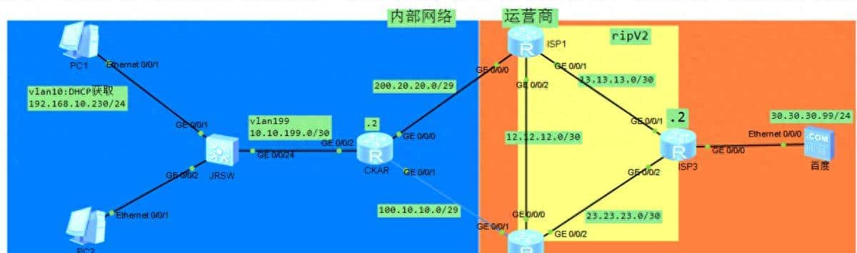
1.2 网络中各设备的IP地址规划及接口描述如下:
|
设备名称 |
接口 |
IP地址 |
VLAN ID |
备注 |
|
JRSW |
GE0/0/1 |
—— |
10 |
连接PC1的接口,添加到VLAN10 |
|
GE0/0/2 |
—— |
20 |
连接PC2的接口,添加到VLAN20 |
|
|
GE0/0/24 |
—— |
199 |
连接出口路由器的接口 |
|
|
Vlanif10 |
192.168.10.254/24 |
10 |
PC1的网关地址 |
|
|
Vlanif20 |
172.16.20.254/24 |
20 |
PC2的网关地址 |
|
|
Vlanif199 |
10.10.199.1/30 |
199 |
连接SW2的接口 |
|
|
CKAR |
GE0/0/0 |
200.20.20.2/29 |
—— |
连接运营商ISP1的接口 |
|
GE0/0/1 |
100.10.10.2/29 |
—— |
连接运营商ISP2的接口 |
|
|
GE0/0/2 |
10.10.199.2/30 |
—— |
连接内部交换机的接口 |
|
|
PC1 |
Eth |
192.168.10.230/24 |
—— |
网关是192.168.10.254 |
|
PC2 |
Eth |
172.16.20.1/24 |
—— |
网关是172.16.20.254 |
二、实验需求
1、PC1及PC2是两种不同业务的PC,分别处于两个VLAN:10及20。PC要求能够正常访问外网;
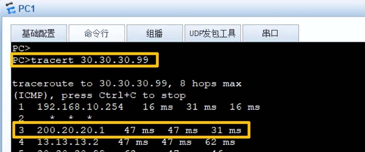
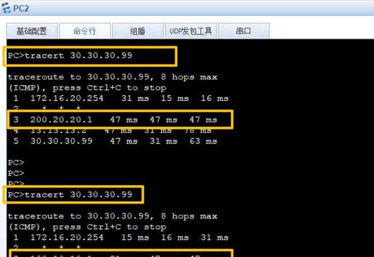
2、当网络正常时,PC1上网时的流量走JRSW>CKAR>ISP1>ISP2>百度的路径,而PC2上网时的流量走JRSW>CKAR>ISP2>ISP2>百度的路径;
3、vlan10的PC终端采用DHCP获取IP地址,vlan20的PC终端采取静态IP配置。
三、实验配置
3.1 配置运营商设备
#
ISP1的配置如下:
sysname ISP1
#
interface GigabitEthernet0/0/0
ip address 200.20.20.1 255.255.255.248
#
interface GigabitEthernet0/0/1
description to ISP2G0/0/1
ip address 13.13.13.1 255.255.255.252
#
interface GigabitEthernet0/0/2
description to ISP2G0/0/0
ip address 12.12.12.1 255.255.255.252
#
interface LoopBack0
ip address 1.1.1.1 255.255.255.252
#
rip 1
version 2
network 12.0.0.0
network 13.0.0.0
network 1.0.0.0
import-route direct
#
ISP2的配置如下:
sysname ISP2
#
interface GigabitEthernet0/0/0
description to ISP1G0/0/0
ip address 12.12.12.2 255.255.255.252
#
interface GigabitEthernet0/0/1
ip address 100.10.10.1 255.255.255.252
#
interface GigabitEthernet0/0/2
description to ISP3G0/0/0
ip address 23.23.23.1 255.255.255.252
#
interface LoopBack0
ip address 2.2.2.2 255.255.255.255
#
rip 1
version 2
network 12.0.0.0
network 23.0.0.0
network 2.0.0.0
import-route direct
#
ISP3的配置如下:
sysname ISP3
#
interface GigabitEthernet0/0/0
description to baidu_IP
ip address 30.30.30.254 255.255.255.0
#
interface GigabitEthernet0/0/1
description to ISP1G0/0/1
ip address 13.13.13.2 255.255.255.252
#
interface GigabitEthernet0/0/2
description to ISP2G0/0/2
ip address 23.23.23.2 255.255.255.252
#
interface LoopBack0
ip address 3.3.3.3 255.255.255.255
#
rip 1
version 2
network 13.0.0.0
network 23.0.0.0
network 3.0.0.0
import-route direct
#
3.2 完成内部JRSW、S及CKAR的基础配置
#
JRSW1:
#
sysname JRSW
#
undo info-center enable #关闭烦人的日志弹出
#
vlan batch 10 20 199
#
dhcp enable
#
dhcp snooping enable
#
vlan 10
description to PC1_IP
dhcp snooping enable
vlan 20
description to PC2_IP
vlan 199
description JKVLAN
#
ip pool vlan10
gateway-list 192.168.10.254
network 192.168.10.0 mask 255.255.255.0
excluded-ip-address 192.168.10.231 192.168.10.253
lease day 2 hour 0 minute 0
dns-list 8.8.8.8 114.114.114.114
#
interface Vlanif10
ip address 192.168.10.254 255.255.255.0
dhcp select global
#
interface Vlanif20
ip address 172.16.20.254 255.255.255.0
#
interface Vlanif199
ip address 10.10.199.1 255.255.255.252
#
interface GigabitEthernet0/0/1
description to PC1
port link-type access
port default vlan 10
#
interface GigabitEthernet0/0/2
description to PC2
port link-type access
port default vlan 20
#
interface GigabitEthernet0/0/24
description to CKAR
port link-type access
port default vlan 199
#
ip route-static 0.0.0.0 0.0.0.0 10.10.199.2
#
CKAR:
#
sysname CKAR
#
interface GigabitEthernet0/0/0
description to ISP1
ip address 200.20.20.2 255.255.255.248
#
interface GigabitEthernet0/0/1
description to ISP2
ip address 100.10.10.2 255.255.255.248
#
interface GigabitEthernet0/0/2
description th JRSWG0/0/24
ip address 10.10.199.2 255.255.255.252
#
ip route-static 0.0.0.0 0.0.0.0 200.20.20.1 description ISP1
ip route-static 0.0.0.0 0.0.0.0 100.10.10.1 description ISP2
ip route-static 172.16.20.0 255.255.255.0 10.10.199.1
ip route-static 192.168.10.0 255.255.255.0 10.10.199.1
#
#配置nat策略
#
acl number 2000
rule 5 permit source 192.168.10.0 0.0.0.255
rule 10 permit source 172.16.20.0 0.0.0.255
#
interface GigabitEthernet0/0/0
nat outbound 2000
#
interface GigabitEthernet0/0/1
nat outbound 2000
#
经过上述配置,终端设备已能顺畅访问外部网络,核心路由器会依据预设策略智能选路 —— 日常状态下,办公终端与服务器流量将按规划分别通过双出口负载分担,最大化利用带宽资源;若某一链路突发故障,系统会在毫秒级时间内自动切换至备用链路,全程无需人工干预,确保终端用户的外网访问体验持续稳定、无感知中断。
PC1:
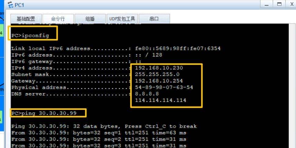
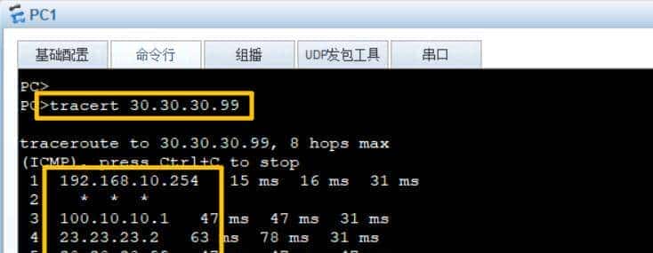
PC1的流量走向:
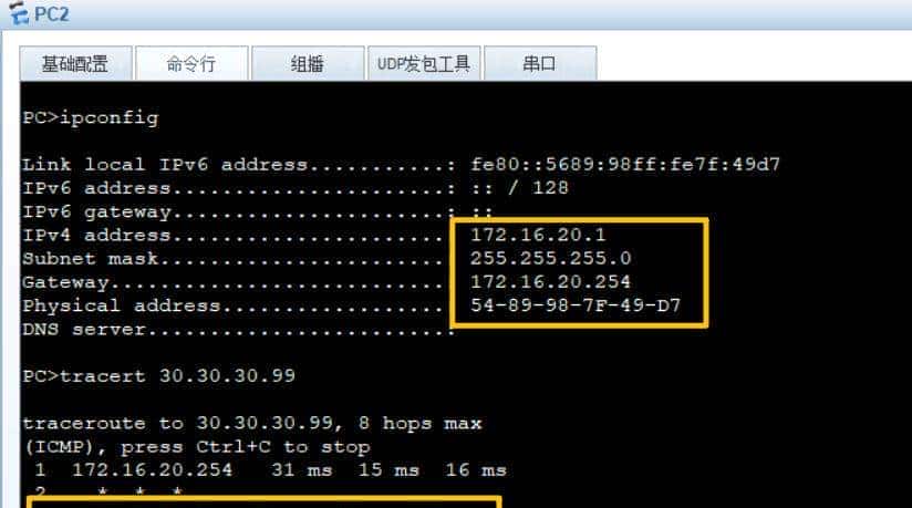
PC2的流量走向:
#
3.3 在出口路由器配置策略路由来实现负载分担
#
CKAR的配置如下:
# 创建两个ACL,分别用来匹配PC1及PC2所在的网段
acl number 2001
description to ISP1
rule 5 permit source 192.168.10.0 0.0.0.255
acl number 2002
description to ISP2
rule 5 permit source 172.16.20.0 0.0.0.255
# 配置两个traffic分类,分别匹配上述两个ACL,实际上就是匹配PC1及PC2所在网段
traffic classifier ISP1 operator or
if-match acl 2001
traffic classifier ISP2 operator or
if-match acl 2002
# 配置两个traffic动作,分别修改下一跳为200.20.20.1及100.10.10.1
traffic behavior ISP2
redirect ip-nexthop 200.20.20.1
traffic behavior ISP1
redirect ip-nexthop 100.10.10.1
# 配置traffic policy,将ISP1流量与动作ISP1捆绑,将ISP2流量与ISP2捆绑
traffic policy SW
classifier ISP1 behavior ISP1
classifier ISP2 behavior ISP2
# 在CKAR的G0/0/2接口入方向调用,同时在接口上应用定义好的traffic policy
interface GigabitEthernet0/0/2
traffic-policy mypolicy inbound
#
PC1的流量走向:
Pc2的流量走向:
© 版权声明
文章版权归作者所有,未经允许请勿转载。


收藏了,感谢分享