
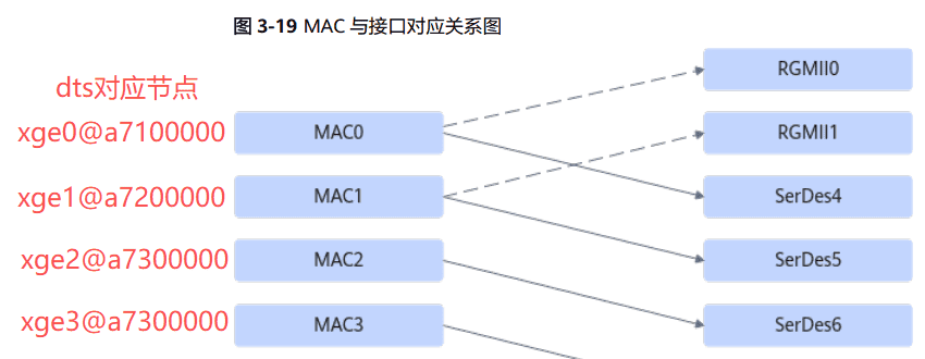
Atlas 200I A2 加速模块有2个RGMII接口和4个SGMII接口,其中4个SGMII接口可由SERDES4~SERDES7复用 ;加速模块内部集成4个MAC,MAC与硬件接口的对应关系可以通过软件配置。根据SerDes的配置不同,网口可以被映射成下面两个配置。
**配置1:**当配置文件中lan_order配为1,且SERDES6、 SERDES7配置为SGMII时, MAC与硬件接口的对应关系为实线连接的对应方式。若SERDES6、 SERDES7不配置为SGMII,则MAC0、 MAC1的对应关系如虚线所示。
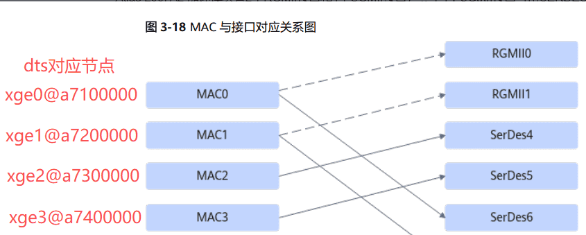
**配置2:**当配置文件中lan_order配为0,且SerDes4、 SERDES5配置为SGMII时, MAC与硬件接口的对应关系为实线连接的对应方式。若SerDes4、 SERDES5不配置为SGMII,则MAC0、 MAC1的对应关系如虚线所示。
硬件上选择两路RGMII信号连接两路switch(yt9215),serDes4通过SGMII连接一路phy(yt8521),这样的话就需要选择配置1的方式来进行配。
下面以实际硬件电路为例对sdk代码进行修改。
修改serdes配置文件”config/adaptive/adaptive_config/user_base_config.xml”
<!-- 部分代码 -->
<submodule subclass="serdes_info">
     <param lan_index="0" serdes_type="PCIE" ssc_enable="0" polarity_tx = "0" polarity_rx = "0" lan_order = "0" bandwidth="1"  align_mode="0" frequency="PCIE_GEN2" port_index = "0"/>
     <param lan_index="1" serdes_type="SATA" ssc_enable="1" polarity_tx = "0" polarity_rx = "0" lan_order = "0" bandwidth="ff" align_mode="0" frequency="SATA3.0" port_index = "0"/>
     <param lan_index="2" serdes_type="SATA" ssc_enable="1" polarity_tx = "0" polarity_rx = "0" lan_order = "0" bandwidth="ff" align_mode="0" frequency="SATA3.0" port_index = "0"/>
     <param lan_index="3" serdes_type="PCIE" ssc_enable="0" polarity_tx = "0" polarity_rx = "0" lan_order = "0" bandwidth="1" align_mode="0" frequency="PCIE_GEN2" port_index = "0"/>
     <param lan_index="4" serdes_type="ETH" ssc_enable="0" polarity_tx = "0" polarity_rx = "0" lan_order = "1" bandwidth="ff"  align_mode="0" frequency="1GE" port_index = "0"/>
     <param lan_index="5" serdes_type="ETH" ssc_enable="0" polarity_tx = "0" polarity_rx = "0" lan_order = "1" bandwidth="ff"  align_mode="0" frequency="1GE" port_index = "0"/>
     <param lan_index="6" serdes_type="USB"  ssc_enable="0" polarity_tx = "0" polarity_rx = "0" lan_order = "0" bandwidth="ff" align_mode="0" frequency="USB3.0" port_index = "0"/>
     <param lan_index="7" serdes_type="USB"  ssc_enable="0" polarity_tx = "0" polarity_rx = "0" lan_order = "0" bandwidth="ff" align_mode="0" frequency="USB3.0" port_index = "0"/>
</submodule>
注意网口配置中lan_order的选择。
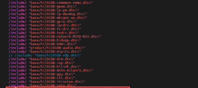
修改dts文件”dtb/dts/hi1910b/hi1910BL/base/hi1910B-network-M150-B33.dtsi”
        eth0:xge0@a7100000 {
                compatible = "hisilicon,hns3-platform-device"; //有些网口默认是关闭的,这个值不对,如果需要启用,请修改的和这个一样。
                id = <0>;
                reg = <0x0 0xa7100000 0x0 0x10000>,
                          <0x0 0xa7000000 0x0 0x800000>,
                          <0x0 0xa0120000 0x0 0x10000>,
                          <0x0 0xa0180000 0x0 0x10000>,   //这个是MDIO接口的地址,根据自己实际情况选择,这里这个是第一路mdio
                          <0x0 0xa0160000 0x0 0x10000>,
                          <0x0 0xa0150000 0x0 0x10000>,
                          <0x0 0xa0140000 0x0 0x10000>,
                          <0x0 0xa0100000 0x0 0x10000>;
                reg-names = "network_base";
                //249 +#253 - 32 = 0xdd
                interrupts = <
                0x0 0xd9 0x1
                0x0 0xda 0x1
                0x0 0xdb 0x1
                0x0 0xdc 0x1
                0x0 0xdd 0x1
                0x0 0xde 0x1
                0x0 0xdf 0x1
                0x0 0xe0 0x1
                0x0 0xe1 0x1
                0x0 0xe2 0x1
                0x0 0xe3 0x1
                0x0 0xe4 0x1
                0x0 0xe5 0x1
                0x0 0xe6 0x1
                0x0 0xe7 0x1
                0x0 0xe8 0x1
                0x0 0xe9 0x4
                0x0 0xed 0x4
                0x0 0xd1 0x4>;
                status = "ok";
                tc_num = <4>;    //tc_num驱动中有限制,4个网口的值之和不能超过16.
                queue_num = <4>;  //queue_num同上面tc_num.
                gpio_index = <6>;
                phy_addr = <255>;  //这个接的switch,地址写的255后面介绍原因
                phy_mode = <1>; // 0:sgmii 1:rgmii 2:sfp
                port_speed = <1000>; // 10: 10M, 100: 100M, 1000: 1G; 2500: 2.5G(only phy_mode sfp support)
                ds_index = <2>;
                phy_gpio_index = <12>;
        };
        eth1:xge1@a7200000 {
                compatible = "hisilicon,hns3-platform-device";
                id = <1>;
                reg = <0x0 0xa7200000 0x0 0x10000>,
                          <0x0 0xa7000000 0x0 0x800000>,
                          <0x0 0xa0120000 0x0 0x10000>,
                          <0x0 0xa0190000 0x0 0x10000>,     //这里这个是第二路mdi0
                          <0x0 0xa0160000 0x0 0x10000>,
                          <0x0 0xa0150000 0x0 0x10000>,
                          <0x0 0xa0140000 0x0 0x10000>,
                          <0x0 0xa0100000 0x0 0x10000>;
                reg-names = "network_base";
                //249 +#253 - 32 = 0xdd
                interrupts = <
                0x0 0xd9 0x1
                0x0 0xda 0x1
                0x0 0xdb 0x1
                0x0 0xdc 0x1
                0x0 0xdd 0x1
                0x0 0xde 0x1
                0x0 0xdf 0x1
                0x0 0xe0 0x1
                0x0 0xe1 0x1
                0x0 0xe2 0x1
                0x0 0xe3 0x1
                0x0 0xe4 0x1
                0x0 0xe5 0x1
                0x0 0xe6 0x1
                0x0 0xe7 0x1
                0x0 0xe8 0x1
                0x0 0xea 0x4
                0x0 0xee 0x4
                0x0 0xd2 0x4>;
                status = "ok";
                tc_num = <4>;
                queue_num = <4>;
                gpio_index = <9>;
                phy_addr = <255>;
                phy_mode = <1>; // 0:sgmii 1:rgmii 2:sfp
                port_speed = <1000>; // 10: 10M, 100: 100M, 1000: 1G; 2500: 2.5G(only phy_mode sfp support)
                ds_index = <3>;
                phy_gpio_index = <25>;
        };
        xge2@a7300000 {
                pinctrl-names = "default", "idle";
                pinctrl-0 = <&gpio3_1_pmx_func &gpio3_1_pmx_idle>;
                compatible = "hisilicon,hns3-platform-device";
                id = <2>;
                reg = <0x0 0xa7300000 0x0 0x10000>,
                          <0x0 0xa7000000 0x0 0x800000>,
                          <0x0 0xa0120000 0x0 0x10000>,
                          <0x0 0xa0180000 0x0 0x10000>, //这里同样是第一路mdio
                          <0x0 0xa0160000 0x0 0x10000>,
                          <0x0 0xa0150000 0x0 0x10000>,
                          <0x0 0xa0140000 0x0 0x10000>,
                          <0x0 0xa0100000 0x0 0x10000>;
                reg-names = "network_base";
                //249 +#253 - 32 = 0xdd
                interrupts = <
                0x0 0xd9 0x1
                0x0 0xda 0x1
                0x0 0xdb 0x1
                0x0 0xdc 0x1
                0x0 0xdd 0x1
                0x0 0xde 0x1
                0x0 0xdf 0x1
                0x0 0xe0 0x1
                0x0 0xe1 0x1
                0x0 0xe2 0x1
                0x0 0xe3 0x1
                0x0 0xe4 0x1
                0x0 0xe5 0x1
                0x0 0xe6 0x1
                0x0 0xe7 0x1
                0x0 0xe8 0x1
                0x0 0xeb 0x4
                0x0 0xef 0x4
                0x0 0xd3 0x4>;
                status = "ok";
                tc_num = <4>;
                queue_num = <4>;
                gpio_index = <6>;
                phy_addr = <0xff>;
                phy_mode = <0>; // 0:sgmii 1:rgmii 2:sfp
                port_speed = <1000>; // 10: 10M, 100: 100M, 1000: 1G; 2500: 2.5G(only phy_mode sfp support)
                ds_index = <0>;
                //phy_gpio_index = <0xff>;  //phy_gpio_index定义后,phy-reset-gpio将失效。
                phy-reset-gpio = <&gpio3 1 0>;
        };
        xge3@a7400000 {
                compatible = "hisilicon,hns3-platform-device3";
                id = <3>;
                reg = <0x0 0xa7400000 0x0 0x10000>,
                          <0x0 0xa7000000 0x0 0x800000>,
                          <0x0 0xa0120000 0x0 0x10000>,
                          <0x0 0xa0180000 0x0 0x10000>,
                          <0x0 0xa0160000 0x0 0x10000>,
                          <0x0 0xa0150000 0x0 0x10000>,
                          <0x0 0xa0140000 0x0 0x10000>,
                          <0x0 0xa0100000 0x0 0x10000>;
                reg-names = "network_base";
                //249 +#253 - 32 = 0xdd
                interrupts = <
                0x0 0xd9 0x1
                0x0 0xda 0x1
                0x0 0xdb 0x1
                0x0 0xdc 0x1
                0x0 0xdd 0x1
                0x0 0xde 0x1
                0x0 0xdf 0x1
                0x0 0xe0 0x1
                0x0 0xe1 0x1
                0x0 0xe2 0x1
                0x0 0xe3 0x1
                0x0 0xe4 0x1
                0x0 0xe5 0x1
                0x0 0xe6 0x1
                0x0 0xe7 0x1
                0x0 0xe8 0x1
                0x0 0xec 0x4
                0x0 0xf0 0x4
                0x0 0xd4 0x4>;
                status = "ok";
                tc_num = <4>;
                queue_num = <4>;
                gpio_index = <9>;
                phy_addr = <255>;
                phy_mode = <0>; // 0:sgmii 1:rgmii 2:sfp
                port_speed = <1000>; // 10: 10M, 100: 100M, 1000: 1G; 2500: 2.5G(only phy_mode sfp support)
                ds_index = <1>;
                phy_gpio_index = <0xff>;
        };
注意:需要根据硬件配置好pcie的dts,不然可能会导致系统卡死或重启。最简单的方式就是先注释掉pcie相关的dts。另外mdio的那个dts也没啥用,如果用户需要自己实现mdio的读写这个可以派上用场,实际我们这里用到mdio读写在网卡的驱动中已经集成。
yt8521(phy)移植
关于yt8521在网卡驱动(Ascend310B-source/driver/drivers/network/platform_pf)中已经做适配,主要实现的是一些PHY初始化的配置,如果需要调整相关的配置时,可在源码基础上进行修改,下面是我添加的一些功能。
1.驱动中为yt8521提供了一个写函数,可用来测试MDIO读写yt8521是否正常。
diff --git a/platform_phy.c b/platform_phy.c
index ff6697e..1d19c66 100644
--- a/platform_phy.c
+++ b/platform_phy.c
@@ -212,6 +212,16 @@ STATIC int hns_yt8521_ext_reg_cfg(struct phy_device *phydev, u32 reg, u16 set)
     return hns_phy_modify(phydev, MOTORCOMM_EXT_DATA_REG, 0xffff, set);
 }

+STATIC int hns_yt8521_ext_reg_read(struct phy_device *phydev, u32 reg)
+{
+    int ret;
+    ret = hns_phy_modify(phydev, MOTORCOMM_EXT_OFFSET_REG, 0xffff, (u16)reg);
+    if (ret != 0) {
+       return ret;
+    }
+    return phy_read(phydev, MOTORCOMM_EXT_DATA_REG);
+}
+
 STATIC int hns_yt8521_led_cfg(struct phy_device *phydev)
 {
 #define MOTORCOMM_LED0_CFG_EX_REG 0xa00c
@@ -248,12 +258,14 @@ int hns_yt8521_config_init(struct phy_device *phydev)
 {
     int ret;

+    ret = hns_yt8521_ext_reg_read(phydev, 0xa001);
+    pr_info("xge %s enter hw_strap_mode=0x%04x
",__func__,ret);
+
     ret = hns_yt8521_delay_and_driver_cfg(phydev);
     if (ret != 0) {
         pr_err("failed to config delay & driver, ret:%d
", ret);
         return ret;
     }

     return hns_yt8521_led_cfg(phydev);
 }
2.增加可通过普通的gpio引脚来控制PHY reset。
diff --git a/hclge_plf_main.c b/hclge_plf_main.c
index fe52299..fb3b695 100755
--- a/hclge_plf_main.c
+++ b/hclge_plf_main.c
@@ -5,6 +5,7 @@
  * Create: 2021-12-28
  */

+#include <linux/gpio.h>
 #include <linux/acpi.h>
 #include <linux/device.h>
 #include <linux/etherdevice.h>
@@ -20,6 +21,7 @@
 #include <net/ipv6.h>
 #include <net/rtnetlink.h>
 #include <linux/of.h>
+#include <linux/of_gpio.h>
 #include <linux/vmalloc.h>
 #include <linux/kallsyms.h>
 #ifdef CONFIG_PLATFORM_MDC
@@ -805,26 +807,32 @@ STATIC int hclge_plf_init_hw(struct hclge_plf_dev *hdev)
     return 0;
 }

+#define INVALID_GPIO_INDEX 0xff
 STATIC void hclge_plf_phy_gpio_init(struct hclge_plf_dev *hdev)
 {
-#define INVALID_GPIO_INDEX 0xff
     void __iomem *gpio_base;
-    u32 gpio_index;
+    u32 gpio_index, phy_reset;

     gpio_base = hdev->hw.mac.phy_gpio_base;
     gpio_index = hdev->hw.mac.phy_gpio_index;
+    phy_reset = hdev->hw.mac.phy_reset_gpio;

     if (gpio_index == INVALID_GPIO_INDEX) {
-        return;
-    }
-
-    gpio_phy_init(gpio_base, gpio_index);
+       if(!gpio_is_valid(phy_reset))
+               return;
+       gpio_set_value(phy_reset, 0);
+       usleep_range(20000, 20000); // 20ms(20000 us)
+       gpio_set_value(phy_reset, 1);
+       usleep_range(80000, 80000); // 80ms(80000 us)
+    } else {
+       gpio_phy_init(gpio_base, gpio_index);

-    /* reset PHY */
-    gpio_set(gpio_base, gpio_index, 0);
-    usleep_range(20000, 20000); // 20ms(20000 us)
-    gpio_set(gpio_base, gpio_index, 1);
-    usleep_range(80000, 80000); // 80ms(80000 us)
+       /* reset PHY */
+       gpio_set(gpio_base, gpio_index, 0);
+       usleep_range(20000, 20000); // 20ms(20000 us)
+       gpio_set(gpio_base, gpio_index, 1);
+       usleep_range(80000, 80000); // 80ms(80000 us)
+    }
 }

 STATIC void hclge_plf_tpu_init(struct hclge_plf_dev *hdev)
 @@ -1089,8 +1097,20 @@ STATIC int hclge_plf_get_cap(struct hclge_plf_dev *hdev)

     ret = of_property_read_u32(pdev->dev.of_node, "phy_gpio_index", &tmp);
     if (ret != 0) {
-        dev_err(&pdev->dev, "failed to get phy_gpio_index, ret = %d
", ret);
-        return ret;
+        dev_warn(&pdev->dev, "failed to get phy_gpio_index, ret = %d. Will attempt to obtain the phy-reset-gpio.
", ret);
+       hdev->hw.mac.phy_reset_gpio = of_get_named_gpio(pdev->dev.of_node, "phy-reset-gpio", 0);
+       if(gpio_is_valid(hdev->hw.mac.phy_reset_gpio)){
+           ret = devm_gpio_request(&pdev->dev, hdev->hw.mac.phy_reset_gpio, "phy-reset");
+           if(ret){
+               hdev->hw.mac.phy_reset_gpio = -1;
+               dev_err(&pdev->dev, "failed to get phy_reset_gpio, ret = %d
", ret);
+               return ret;
+           }
+           gpio_direction_output(hdev->hw.mac.phy_reset_gpio, 0);
+           tmp = INVALID_GPIO_INDEX;
+       }
+    } else {
+        hdev->hw.mac.phy_reset_gpio = -1;
     }
     hdev->hw.mac.phy_gpio_index = tmp;

diff --git a/hclge_plf_main.h b/hclge_plf_main.h
index 550bbea..7f02e38 100644
--- a/hclge_plf_main.h
+++ b/hclge_plf_main.h
@@ -412,6 +412,7 @@ struct hclge_plf_mac {
     u32 ds_index;
     void __iomem *phy_gpio_base; /* phy_gpio reg base addr */
     u32 phy_gpio_index;
+    u32 phy_reset_gpio;                /*gpio reset phy*/
     atomic_t int_clear_flag; /* when first link up, clear interrupt after initialization */
 };
dts对应修改如下:
//phy_gpio_index = <0xff>;  //phy_gpio_index定义后,phy-reset-gpio将失效。
phy-reset-gpio = <&gpio3 1 0>;
问题一:
网口可以正常UP和设置固定IP,但是无法ping通。调整过PHY的delay和驱动能力,但是均没有效果,从yt8521的数据手册可以看到这个调整是针对RGMII接口,所以对SGMII接口可能也没啥效果。经过排查发现是Ascend310B的serdes 100Mhz时钟不支持展频,而硬件上又刚好配置了时钟芯片是展频模式。

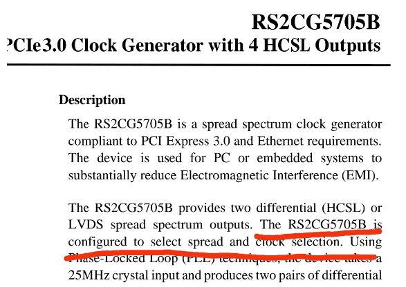
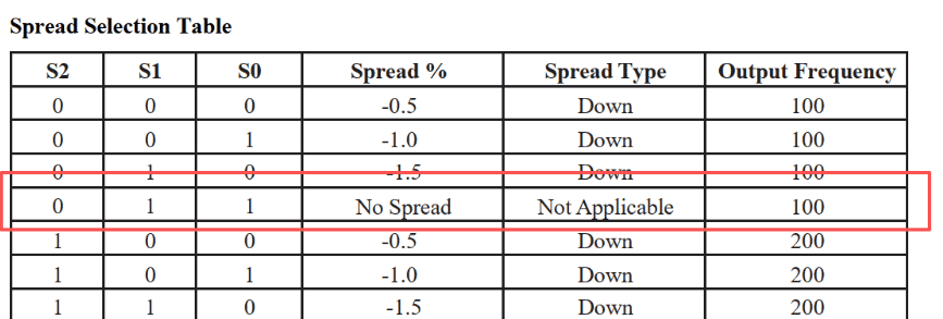
修改时钟芯片的S2~S0引脚的上下拉为011,失能展频功能问题解决。
yt9215(switch)移植
yt9521和Ascend310B之间采用mac to mac的连接方式,并不存在实际的PHY,所以没法通过PHY的那种方式来对yt9521进行初始化配置,所以需要创建一个fixed-link来创建一个虚拟的连接,这样就可以保证网能被正常的UP和配置。然后在通过其它方式实现switch的初始化配置,像yt9215就可以通过MDIO和flash进行配置,不过如果用MDIO配置就需要客户自己去实现这个接口。
在Ascend310B的网卡驱动中没有提供fixed-link的支持,但是有个好的地方,就是可以将phy_addr设置成255,这样驱动中就认为没有PHY设备,但是网口的整个配置流程还继续执行。导致的结果就是虽然没有PHY也没有fixed-link,但是网口可以正常UP和设置,实现了和fixed-link一样的效果。
接下来需要做的就是打通MDIO接口实现对yt9215的初始化配置。这里可以套用内核中专门为switch设备设计的dsa驱动,在dsa驱动中首先会注册一个mdio_driver,通过这个mdio_driver中的probe函数就可以获取到mdiobus,实现mdio的读写。有个mdio_driver相对应的就还需要一个mdio_device,这样才是现实driver和device之间的match。这个mdio_device的注册可以放在Ascend310B网卡驱动中mdiobus注册成功之后并且判断到是switch设备的时候。网卡驱动中代码实现如下:
diff --git a/mdio/hns_mdio_dc.c b/mdio/hns_mdio_dc.c
index 242e98f..c99d48a 100644
--- a/mdio/hns_mdio_dc.c
+++ b/mdio/hns_mdio_dc.c
@@ -7,6 +7,44 @@

 #include "hns_mdio_dc.h"

+
+bool of_mdiobus_child_is_switch(struct device_node *child)
+{
+    if (of_device_is_compatible(child, "ethernet-switch-device"))
+       return true;
+    return false;
+}
+
+static int of_mdiobus_register_device(struct mii_bus *mdio,
+                               struct device_node *child, u32 addr)
+{
+    struct mdio_device *mdiodev;
+    int rc;
+
+    mdiodev = mdio_device_create(mdio, addr);
+    if (IS_ERR(mdiodev))
+       return PTR_ERR(mdiodev);
+    /* Associate the OF node with the device structure so it
+     * can be looked up later.
+     */
+    of_node_get(child);
+    mdiodev->dev.of_node = child;
+    mdiodev->dev.fwnode = of_fwnode_handle(child);
+
+    /* All data is now stored in the mdiodev struct; register it. */
+    rc = mdio_device_register(mdiodev);
+    if (rc) {
+       mdio_device_free(mdiodev);
+        of_node_put(child);
+        return rc;
+    }
+    dev_info(&mdio->dev, "registered mdio device %pOFn at address %i
",
+               child, addr);
+
+    return 0;
+}
+
+
 int hns_mac_mdio_init(struct hclge_plf_dev *hdev)
 {
 #define PHY_INEXISTENT  255
@@ -15,16 +53,19 @@ int hns_mac_mdio_init(struct hclge_plf_dev *hdev)
     struct platform_device *pdev = hdev->pdev;
     struct hclge_plf_mac *mac = &hdev->hw.mac;
     struct hns_mdio_device *mdio_dev = NULL;
+    struct device_node *np = pdev->dev.of_node;
+    struct device_node *child;
     struct phy_device *phydev;
     struct mii_bus *mdio_bus;
+    bool scansw = false;
     u32 tmp_id[TEMP_ID_LEN] = {0};
     u32 phy_id;
-    int ret;
+    int ret, addr;

-    if (hdev->hw.mac.phy_addr == PHY_INEXISTENT) {
-        dev_info(&hdev->pdev->dev, "No phy device is connected to mdio bus
");
-        return 0;
-    }
+//    if (hdev->hw.mac.phy_addr == PHY_INEXISTENT) {
+//        dev_info(&hdev->pdev->dev, "No phy device is connected to mdio bus
");
+//        return 0;
+//    }

     mdio_dev = (struct hns_mdio_device *)devm_kzalloc(&pdev->dev, sizeof(struct hns_mdio_device), GFP_KERNEL);
     if (mdio_dev == NULL) {
@@ -53,6 +94,30 @@ int hns_mac_mdio_init(struct hclge_plf_dev *hdev)
         return ret;
     }

+    if (hdev->hw.mac.phy_addr == PHY_INEXISTENT) {
+       for_each_available_child_of_node(np, child){
+           addr = of_mdio_parse_addr(&mdio_bus->dev, child);
+           if (addr < 0) {
+               continue;
+           }
+           if (!of_mdiobus_child_is_switch(child)) {
+               dev_info(&hdev->pdev->dev, "%s: Not switch device.
", child->name);
+               continue;
+           }
+           ret = of_mdiobus_register_device(mdio_bus, child, addr);
+           if (ret == -ENODEV)
+               dev_err(&mdio_bus->dev,"MDIO device at address %d is missing.
",
+                                   addr);
+           else
+               scansw = true;
+       }
+       if (!scansw) {
+               dev_err(&mdio_bus->dev,"switch node not found
");
+               mdiobus_unregister(mdio_bus);
+       }
+       return 0;
+    }
+
     phydev = mdiobus_get_phy(mdio_bus, mac->phy_addr);
     if (!phydev) {
         dev_err(mdio_bus->parent, "Failed to get phy device
");
yt9215驱动代码如下:
#include <linux/proc_fs.h>
#include <linux/module.h>
#include <linux/cdev.h>
#include <linux/device.h>
#include <linux/of_mdio.h>
#include <linux/of_net.h>
#include <linux/of_platform.h>
#include <linux/mdio.h>


#define YT9215RB_DEFINE_PHYADDR         0x1D
#define YT9215RB_DEFINE_SWITCHID        0x00


#define YT9215RB_REG_ADDR_BIT1_ADDR     0
#define YT9215RB_REG_ADDR_BIT1_DATA     1
#define YT9215RB_REG_ADDR_BIT0_WRITE    0
#define YT9215RB_REG_ADDR_BIT0_READ     1

#define YT9215RB_RX_DELAY_MASK          (0xf<<3)
#define YT9215RB_TX_DELAY_MASK          (0xf<<13)
#define YT9215RB_TX_DELAY_EN            (1<<8)

#define YT9215RB_TX_STRENGTH_BITS_MASK  0x3FFFF
#define YT9215RB_RX_STRENGTH_BITS_MASK  0x3FFC0000
#define YT9215RB_DR_STRENGTH_BITS_MASK  (YT9215RB_TX_STRENGTH_BITS_MASK | YT9215RB_RX_STRENGTH_BITS_MASK)
#define YT9215RB_MANU_DR_EN             (1<<9)

struct yt9215rb_priv {
        struct device           *dev;
        struct mii_bus          *bus;

        unsigned int            address;
        unsigned int            id;

        unsigned int            strength[2];
        unsigned int            rx_dly;
        unsigned int            tx_dly;
        bool                    tx_en;
        bool                    io_1v8;

        /* protect among processes for registers access*/
        struct mutex            reg_mutex;
};
static int yt9215rb_smi_read32(struct mii_bus *bus, uint32_t phy_id, uint32_t regaddr, uint32_t *regval)
{
        int ret;
        uint16_t lo, hi;
        ret = bus->read(bus, phy_id, regaddr);
        if(ret >= 0){
                hi = (uint16_t)(ret & 0xffff);
                ret = bus->read(bus, phy_id, regaddr);
                lo = (uint16_t)(ret & 0xffff);
        }
        *regval = (uint32_t)((hi<<16) | lo);
        if (ret < 0){
                dev_err(&bus->dev, "failed to read register");
        }
        return ret < 0 ? -1 : 0;
}

static int yt9215rb_smi_write32(struct mii_bus *bus, uint32_t phy_id, uint32_t regaddr, uint32_t regval)
{
        int ret;
        uint16_t lo, hi;

        lo = regval & 0xffff;
        hi = (uint16_t)(regval >> 16);
        ret = bus->write(bus, phy_id, regaddr, hi);
        return (ret < 0 ? ret : bus->write(bus, phy_id, regaddr, lo));
}
static int yt9215rb_read(struct yt9215rb_priv *priv, uint32_t regnum, uint32_t *regval)
{
        int ret;
        uint32_t regaddr;
        struct mii_bus *bus = priv->bus;

        /* set reg address*/
        regaddr = (priv->id<<2)|(YT9215RB_REG_ADDR_BIT1_ADDR<<1)|(YT9215RB_REG_ADDR_BIT0_READ);
        ret = yt9215rb_smi_write32(bus, priv->address, regaddr, regnum);
        if(ret < 0)
                goto exit;

        /* get reg value*/
        regaddr = (priv->id<<2)|(YT9215RB_REG_ADDR_BIT1_DATA<<1)|(YT9215RB_REG_ADDR_BIT0_READ);
        ret = yt9215rb_smi_read32(bus, priv->address, regaddr, regval);
exit:
        mutex_unlock(&priv->reg_mutex);
        if(ret < 0)
                dev_err(&bus->dev, "failed to read register");
        return ret;
}
static int yt9215rb_write(struct yt9215rb_priv *priv, uint32_t regnum, uint32_t regval)
{
        int ret;
        uint32_t regaddr;
        struct mii_bus *bus = priv->bus;

        mutex_lock(&priv->reg_mutex);
        /* set reg address*/
        regaddr = (priv->id<<2)|(YT9215RB_REG_ADDR_BIT1_ADDR<<1)|(YT9215RB_REG_ADDR_BIT0_WRITE);
        ret = yt9215rb_smi_write32(bus, priv->address, regaddr, regnum);
        if(ret < 0)
                goto exit;

        /* set reg value*/
        regaddr = (priv->id<<2)|(YT9215RB_REG_ADDR_BIT1_DATA<<1)|(YT9215RB_REG_ADDR_BIT0_WRITE);
        ret = yt9215rb_smi_write32(bus, priv->address, regaddr, regval);
exit:
        mutex_unlock(&priv->reg_mutex);
        if(ret < 0)
                dev_err(&bus->dev, "failed to write register");
        return ret;
}

static int yt9215rb_mask_write(struct yt9215rb_priv *priv, uint32_t regnum, uint32_t mask, uint32_t set)
{
        int ret = 0;
        uint32_t val = 0;

        ret = yt9215rb_read(priv,regnum, &val);
        if(ret >= 0){
                val &= ~mask;
                val |= set;
                ret = yt9215rb_write(priv, regnum, val);
        }
        return ret;
}
static int yt9215rb_init(struct yt9215rb_priv *priv)
{
        u32 val=0;
        if(priv->io_1v8){
                yt9215rb_write(priv,0x80030,0x0f);    //set rgmii io 1.8v
                dev_info(priv->dev,"setting rgmii io 1.8v");
        }
        yt9215rb_write(priv,0x80394,0x2);
        yt9215rb_write(priv,0x80400,0x841C0000);

        /* set rgmii ports driver strength*/
        if(( priv->strength[0] !=0 ) || (priv->strength[1] !=0)){
                //set manu_dr_en
                yt9215rb_mask_write(priv,0x80358,YT9215RB_MANU_DR_EN,YT9215RB_MANU_DR_EN);

                //set rgmii port1 driver strength
                if( priv->strength[0] !=0 ){
                        yt9215rb_mask_write(priv,0x803ac,YT9215RB_DR_STRENGTH_BITS_MASK,
                                                priv->strength[0]);
                }
                //set rgmii port2 driver strength
                if( priv->strength[1] !=0 ){
                        yt9215rb_mask_write(priv,0x803a8,YT9215RB_DR_STRENGTH_BITS_MASK,
                                                priv->strength[1]);
                }
        }

        val = (priv->rx_dly << 3) | (priv->tx_dly << 13);
        if(priv->tx_en){
                val |= YT9215RB_TX_DELAY_EN;
        } else {
                val &= ~YT9215RB_TX_DELAY_EN;
        }
        yt9215rb_mask_write(priv,0x80400,YT9215RB_RX_DELAY_MASK | YT9215RB_TX_DELAY_MASK | YT9215RB_TX_DELAY_EN,val);
        yt9215rb_write(priv,0x80120,0x1fa);

        return 0;
}
static int yt9215rb_dt(struct yt9215rb_priv *priv, struct device_node *np)
{

        if(of_property_read_u32(np, "address", &priv->address)){
                priv->address = YT9215RB_DEFINE_PHYADDR;
        }
        if(of_property_read_u32(np, "reg", &priv->id)){
                priv->id = YT9215RB_DEFINE_SWITCHID;
        }

        priv->io_1v8 = of_property_read_bool(np,"io-1v8");

        if(of_property_read_u32(np, "tx-delay", &priv->tx_dly)){
                priv->tx_en = false;
        } else {
                priv->tx_en = true;
                if(priv->tx_dly > 0x0f){
                        dev_warn(priv->dev,"yt9215 set tx_dly value error! range <0 ~ 0x0f>");
                        priv->tx_dly = 2;
                }
        }
        if(of_property_read_u32(np, "rx-delay", &priv->rx_dly)){
                priv->rx_dly = 1;
        } else {
                if(priv->rx_dly > 0x0f){
                        dev_warn(priv->dev,"yt9215 set rx_dly value error! range <0 ~ 0x0f>");
                        priv->rx_dly = 1;
                }
        }

        if(of_property_read_u32_array(np, "yt9215,strength", priv->strength,2)){
                priv->strength[0] = 0;
                priv->strength[1] = 0;
        } else {
                dev_info(priv->dev,"yt9215 set driver strength, value:<0x%08x, 0x%08x>.",
                                priv->strength[0], priv->strength[1]);
        }
        return 0;
}
static const struct of_device_id yt9215rb_of_match[] = {
        { .compatible = "motorcomm,yt9215rb",},
        { /* sentinel */ },
};
MODULE_DEVICE_TABLE(of, yt9215rb_of_match);

static int yt9215rb_probe(struct mdio_device *mdiodev)
{
        struct yt9215rb_priv *priv;
        struct device_node   *dn = mdiodev->dev.of_node;

        printk("Lee yt9215 driver....
");

        priv = devm_kzalloc(&mdiodev->dev, sizeof(struct yt9215rb_priv), GFP_KERNEL);
        if (!priv)
                return -ENOMEM;
        priv->bus = mdiodev->bus;
        priv->dev = &mdiodev->dev;

        yt9215rb_dt(priv, dn);
        mutex_init(&priv->reg_mutex);
        yt9215rb_init(priv);

        return 0;
}


static void yt9215rb_remove(struct mdio_device *mdiodev)
{

}

static struct mdio_driver yt9215rb_mdio_driver = {
        .probe  = yt9215rb_probe,
        .remove = yt9215rb_remove,
        .mdiodrv.driver = {
                .name = "yt9215rb",
                .of_match_table = yt9215rb_of_match,
        },
};

mdio_module_driver(yt9215rb_mdio_driver);

MODULE_AUTHOR("Sean Wang <sean.wang@mediatek.com>");
MODULE_DESCRIPTION("Driver for Mediatek TY9215RB Switch");
MODULE_LICENSE("GPL");
dts中修改如下:
ð0 {
pinctrl-names = "default", "idle";
pinctrl-0 = <&mdc0_cfg_func &mdio0_cfg_func>;
pinctrl-1 = <&mdc0_cfg_func &mdio0_cfg_func>;
switch0: switch@0 {
compatible = "ethernet-switch-device","motorcomm,yt9215rb";
#address-cells = <1>;
#size-cells = <0>;
reg = <0>;
address = <0x1D>;
yt9215,strength = <0x1557b6db 0>;
rx-delay = <0x01>;
tx-delay = <0x01>;
io-1v8;
};
};
ð1 {
pinctrl-names = "default", "idle";
pinctrl-0 = <&mdc1_cfg_func &mdio1_cfg_func>;
pinctrl-1 = <&mdc1_cfg_func &mdio1_cfg_func>;
switch1: switch@1 {
compatible = "ethernet-switch-device","motorcomm,yt9215rb";
#address-cells = <1>;
#size-cells = <0>;
reg = <1>;
address = <0x1D>;
yt9215,strength = <0x1557b6db 0>;
rx-delay = <0x02>;
tx-delay = <0x04>;
io-1v8;
};
};
可以看出上面的实现过程其实和是SGMII还是RGMII没有关系。只要确定网卡能实现类似fixed-link的连接,然后通过上面的方式将mdio的读写操作传递到switch中的驱动即可。关于这部分想了解更多可以参考之前的《RK3568 + YT9215交换机芯片调试》文章。
至此yt9215和yt8521移植完成,通过iperf可以测试,网口速率也符合要求。
© 版权声明
文章版权归作者所有,未经允许请勿转载。
相关文章


暂无评论...